In the production of TFT-LCD displays, the backlight module is one of the core components, and the diffuser film, as a crucial optical material, directly affects the overall display effect.
If the LCD backlight diffuser is chosen incorrectly, it may lead to defects such as uneven display, bright edges, or white spots. These problems often stem from mismatches between the diffuser film and the light guide plate or other components.
As a professional manufacturer of commercial LCD displays, we frequently receive inquiries from customers regarding this issue. Today, we will share some experience to help you avoid risks during the selection phase and ensure a stable and reliable backlight system.
Structural And Selection Requirements For The Top Diffusion Film
The upper diffusion film is typically placed above the brightness enhancement film and below the lower polarizer. Its main function is to prevent adhesion phenomena between the brightness enhancement film and the polarizer, such as Newton's rings or water ripples. It also protects the surface of the brightness enhancement film, optimizes the viewing angle, and improves light softness.
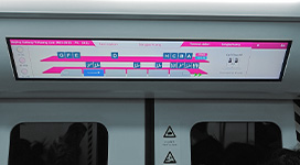
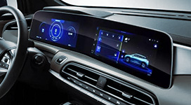
This type of film is commonly found in medium to large-sized products such as high-end laptops, automotive displays, industrial control screens, monitors, and televisions. However, it is generally not used in small devices such as mobile phones, watches, or tablets due to space constraints.
Depending on whether it has a back coating, the upper diffusion film is divided into two categories: with a back coating and without a back coating. When selecting, the type of prism adhesive used in the brightness enhancement film must be considered. If the brightness enhancement film uses elastic adhesive, a top diffusion film with a back coating is preferred to reduce the risk of adhesion. If a rigid adhesive such as diamond adhesive is used, both structures are compatible, which effectively reduces potential defects during assembly.

Bottom LCD Diffusion Film Thickness Selection Requirements
The core structure of the lower LCD diffuser sheet includes a PET substrate, light-emitting surface, and light-receiving surface diffuser particles. The thickness of the PET substrate determines the overall film thickness, directly affecting compatibility with product size. Thickness mismatch can easily lead to film wrinkles, resulting in uneven display.
Based on product size, we recommend the following thicknesses for lower LCD diffusion films:
For small devices such as mobile phones, the mainstream PET substrate thickness for the lower diffusion film is 38μm, with an overall film thickness controlled between 51-55μm. To further reduce the risk of wrinkles, a 50μm substrate can be used, resulting in an overall diffusion film thickness of 62-67μm.
For medium-sized products such as tablets, a 75μm PET substrate thickness and an overall thickness of 90-95μm are recommended.
For medium-sized applications such as automotive or monitor displays, a 100μm PET substrate thickness is preferable, with an overall thickness of 125-130μm.
These choices balance thinness and stability, which is especially important when pursuing narrow bezel designs.
LCD Diffusion Film Particle Material And Particle Size Requirements
Both sides of the LCD display diffusion membrane contain particles, but the requirements for the light-emitting and light-receiving sides differ, directly affecting light diffusion performance and durability.
The particles on the light-emitting side are mostly made of rigid materials, such as PMMA (acrylic) or PS (polystyrene). Lower-end products commonly use PMMA with a particle size of 5-8 μm, while mid-to-high-end products prefer PS with a particle size of approximately 3 μm to achieve finer, more uniform light distribution.
The particles on the light-receiving side can be divided into two types: soft particles and hard particles. Hard particles have a relatively low compressibility, generally controlled between 10% and 20%. This value can easily damage the light guide plate, so it is less commonly used.
Currently, the mainstream particles used on the light-receiving side are soft particles with a compressibility maintained between 30% and 50%, such as PBMA or PA.
PBMA particles are mainly used in low-end products, with an average particle size of 5-8 μm; PA (nylon) particles are mainly used in mid-to-high-end products, with an average particle size of around 5 μm.
It is important to note that the higher the compressibility of the diffuser particles on the light-incident surface, the stronger their resistance to deformation and buffering ability, which can prevent them from damaging the light guide plate. However, a higher compressibility of the diffuser particles is not always better; excessively high compressibility can easily lead to white spots appearing after the diffuser film and light guide plate adhere, as seen with PU (polyurethane) particles.

LCD Diffusion Film Surface Impedance Control Requirements
Static electricity is a common problem with TFT LCD diffusion films, potentially causing white spots, black spots, or foreign matter adhesion. Using films with a surface impedance ≤10^12 Ω significantly improves anti-static performance.
Before assembly, unopened rolls of diffusion film can undergo low-temperature treatment: -15°C to 0°C for 2 hours. This helps reduce static electricity buildup and improve yield, especially in high-humidity environments.
Haze Selection Requirements For The Bottom LCD Diffusion Film
Haze is one of the indicators for evaluating the performance of a diffuser film. Generally speaking, a haze of ≥95% is recommended for the lower LCD backlight diffuser. When the haze is too low, the particle diameter on the incident light surface is larger, making it easier for white spots to be attracted during vacuum adsorption.
Furthermore, during mechanical testing of the LCD screen (micro-drop, roller, directional drop, compression, etc.), the risk of white spots caused by particles damaging the LGP R-CUT surface of the lower LCD backlight diffuser due to pressure from these particles increases.
It is particularly important to note that if the backlight brightness is already close to its limit, high haze may lead to a decrease in luminous efficiency. Therefore, a balance must be struck between uniformity and brightness requirements during the selection process.

Thermal Shrinkage Rate Requirements Of The Bottom LCD Diffusion Film
During the production process, PET film material is heated and subjected to tensile forces in the longitudinal (MD) and transverse (TD) directions. After cooling and shaping, the PET film material can maintain its shape stability at room temperature.
When the PET film material is heated again, it is affected by temperature and the longitudinal (MD) and transverse (TD) tensile forces, resulting in varying degrees of shrinkage in these directions.
This shrinkage process is generally referred to as the material's "thermal shrinkage rate," which is usually irreversible. The formula for calculating the thermal shrinkage rate is: T = (L1 - L2) / L1 * 100%, where L1 represents the size at room temperature, and L2 represents the size after cooling from high temperature to room temperature, in percentage (%).
Generally, a lower coefficient of thermal expansion for the lower diffusion film at the same temperature is better. A lower coefficient of thermal expansion means a smaller dimensional change in the diffusion film from room temperature to high temperature for the same size.
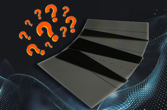
Requirements For Attaching The Black Bar To The Bottom LCD Diffusion Film
In backlights with narrow bezel designs, the lower diffuser film cannot be used alone. Generally, black stripes and black ink screen printing are attached to the lower diffuser film to optimize light effect and prevent displacement.
① A black strip is attached to the light-emitting surface of the lower LCD diffuser sheet. To optimize the backlight source effect and prevent bright edge issues caused by displacement of the lower brightness enhancement film after mechanical testing, a black strip is typically attached to the light-emitting surface of the lower TFT LCD diffusion film. The following requirements apply to the selection of this black strip:
a. The difference in thermal shrinkage rate between the black strip and the diffusion film should be small. A large difference in shrinkage rate between the black strip and the lower diffusion film can lead to wrinkles in the lower diffusion film after reliability testing.
b. The black strip must be cut, but the diffusion film itself should not be cut. It is generally recommended to cut the black strip into 5-7 segments to reduce the impact of shrinkage on the lower diffusion film and prevent wrinkles.
c. The thickness of the black strip is generally around 0.15mm, equivalent to the sum of the thicknesses of the upper and lower brightness enhancement films. If it is a composite brightness enhancement film, the thickness of the black strip is generally around 0.1mm.
② Black ink is screen-printed on the light-receiving surface of the lower diffuser film. This black ink is usually screen-printed on the light source end and the opposite side of the light source end of the lower diffuser film.