In the rigorous world of industrial display manufacturing, the difference between a high-end Industrial display reliability solution and a mediocre consumer-grade screen often lies in the invisible microscopic alignment.
Specifically, the synchronization between the IPS LCD technology panel and its Polarizer absorption axis is the "silent architect" of contrast ratio, thermal stability, and overall optical performance. For system integrators and hardware engineers, understanding these principles is not just about theory; it is about ensuring that a mission-critical display maintains its integrity under 24/7 operation in harsh environments.
The Function Of Polarizer
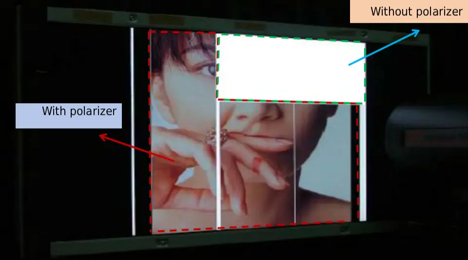
A polarizer, conceptually, is an optical filter that converts non-polarized natural light into linear polarized light. In an industrial display solutions context, polarizers are laminated on the top and bottom surfaces of the glass substrates.
The liquid crystal molecules act as a controllable valve for this polarized light. To achieve the highest efficiency, we must adhere to Malus' Law, which dictates that the intensity of light passing through two polarizers is proportional to the square of the cosine of the angle between their transmission axes.
When the absorption axes are parallel, transmission is maximized; when orthogonal (90 degrees), light is blocked, creating the "Dark State."
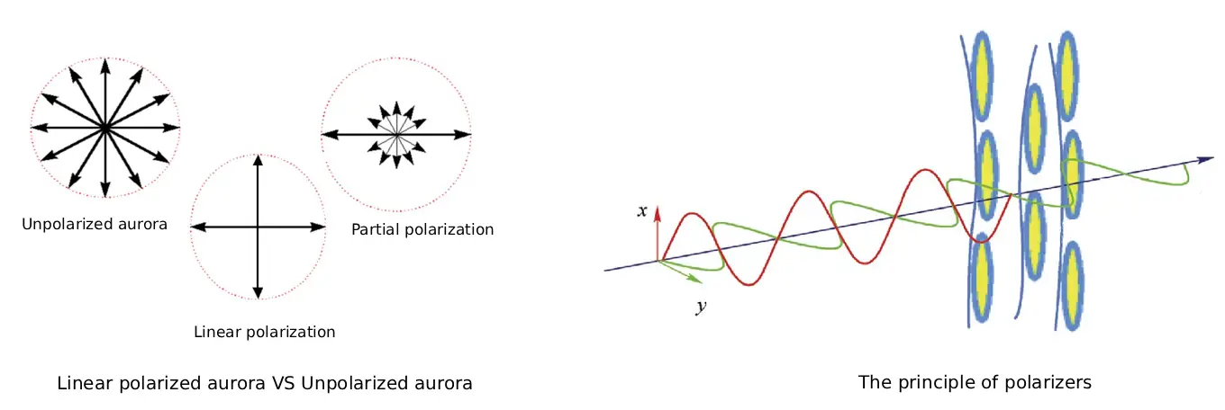
The structural integrity of a polarizer relies on a Polyvinyl Alcohol (PVA) molecular film, typically dyed with iodine molecules or dichroic dyes.
During manufacturing, the PVA film is stretched in a single direction, causing the elongated iodine molecules (specifically $I_3^-$ and $I_5^-$ ions) to align linearly. $I_3^-$ ions primarily absorb blue light, while $I_5^-$ ions target the red spectrum.
This molecular alignment creates the Polarizer absorption axis. Any deviation in this alignment—even by more than the critical 0.8° tolerance—can lead to light leakage and a catastrophic drop in the contrast ratio of an Industrial grade monitor.
IPS Mode LCD Display Principle
IPS LCD technology, or In-plane switching, revolutionized the market by placing both the pixel electrode and the common electrode on the same TFT Array substrate.
Unlike legacy TN modes where molecules twist vertically, IPS molecules rotate horizontally within the plane of the substrate. This horizontal rotation is the secret behind the Wide viewing angle display performance that bar LCD displays are famous for.
However, this horizontal rotation requires precise Liquid crystal alignment. Without a voltage, the molecules must align in a specific direction dictated by the Polyimide (PI) alignment film.
If the initial alignment were perfectly parallel to the electrodes, the molecules would rotate unpredictably, leading to visual artifacts and inconsistent Backlight transmission.
To prevent this, we utilize a "rubbing" process on the PI film to establish a pre-defined angle. This ensures that when the electric field is applied, the "molecular dance" is synchronized and uniform across the entire panel.
O-Mode And E-Mode
In industrial display engineering, we categorize the relationship between the rubbing direction and the polarizer axis into two primary modes: O-mode and E-mode.
The O-mode vs E-mode LCD selection is a critical pivot point for optimizing Black level uniformity. In O-mode, the absorption axis of the bottom polarizer is parallel to the rubbing direction of the TFT substrate.
Conversely, in E-mode, the bottom polarizer's absorption axis is perpendicular to the rubbing direction.
Why does this choice matter? In O-mode, the polarized light entering the liquid crystal layer is an "Ordinary ray," which experiences the ordinary refractive index.
This often results in superior contrast at normal incidence but may require more complex compensation films for wide-angle performance.
E-mode, while slightly different in its optical path, is frequently utilized in high brightness displays where thermal gradients across the panel might affect molecular stability.
For most Industrial LCD display applications, the choice between O and E modes depends on the specific rubbing angle designed during the cell process.
IPS Mode LCD And Polarizer Absorption Axis Matching Principle
Let us delve into the four common scenarios for rubbing directions and how they dictate the Polarizer absorption axis angles. Precision here is non-negotiable, as even a 1° error can degrade LCD viewing angle optimization results.
90° Vertical Rubbing Direction
In an O-mode configuration with a 90° rubbing direction, the bottom polarizer absorption axis is set to 90° (adhesive side up). Since the top and bottom polarizers must be orthogonal, the top polarizer is set to 0° (adhesive side down). For E-mode, the angles are swapped: the bottom is 0°, and the top is 90°. Note that during the cutting process, we must account for "mirroring." For 0° and 90°, the mirror image remains the same.
0° Parallel Rubbing Direction
When the rubbing direction is parallel to the short side (0°), the O-mode requires a 0° bottom polarizer and a 90° top polarizer. The E-mode reverses this to a 90° bottom and a 0° top. Again, the 0.8° tolerance is the boundary between a professional-grade black state and a "cloudy" or "greyish" dark state that plagues lower-quality panels.
Short-Side Off-Axis Rubbing
This is where complexity increases. If the rubbing direction is situated on the short side with an offset (e.g., 173°), the O-mode bottom polarizer starts at 173° (adhesive side up). After mirroring for the cutting process (adhesive side down), the actual cutting angle becomes 7°. The corresponding top polarizer is then set at 83°. In E-mode, the mirrored bottom angle is 97°, and the top is 173°. These precise offsets are vital for maintaining color shift stability in high-end kiosks.
Long-Side Off-Axis Rubbing
TFor long-side rubbing directions (often favored in specific landscape orientations), O-mode requires a mirrored bottom polarizer at 97° and a top polarizer at 173°. E-mode utilizes a mirrored bottom at 7° and a top at 83°. Engineering these specific cuts requires advanced laser cutting equipment that can maintain consistent accuracy across large-format panels.
Conclusion
The alignment of IPS liquid crystals and polarizer absorption axes is a masterclass in engineering precision. From the molecular behavior of iodine ions to the complex mirror-cutting logic of O-mode and E-mode, every step is calculated to maximize optical efficiency.
If your project requires specialized technical consultation regarding IPS LCD technology or high-reliability display systems, our engineering team is ready to assist.